Inside the OSI Strasse Orgel
With a bit of luck, you will never have to open up your OSI
Strasse Orgel, but if service is needed the following information
may be useful. It is based on a short conversation with Paul
Fischer, creator of the organ, and my experiences in performing a
minor, but important repair. Based on some details, Paul
identified our organ as an early one, and the photos may not match
all organs exactly.
All repair work is done from the top and front of the organ.
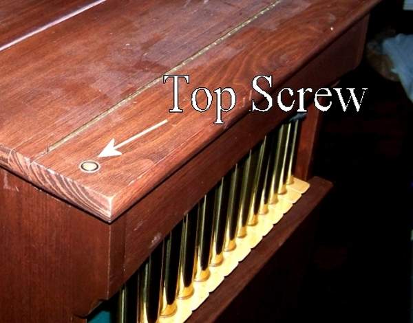
Step 1. Remove the organ's top. If you still have the
original top brace in place, remove at least one end of that
first, then undo the two screws holding the front edge in place
and remove the top.
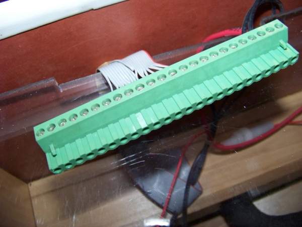
Step 2. Unplug the electronic unit and set it aside. The
same single connector is used with either the MPV-4000
electronic control unit or the Combo Reader upgrade.
Step 3. Pull the screws holding the plexiglass panel in
place, lift the panel, and disconnect wires connecting the charger
to the battery. The details of this connection may vary a bit
depending on whether you have an early or late model. Early models
used a wall-charger and a small plug on the plastic panel. I
understand that on later models the charger was installed in the
organ itself and the 110 volt cord plugged into the panel.
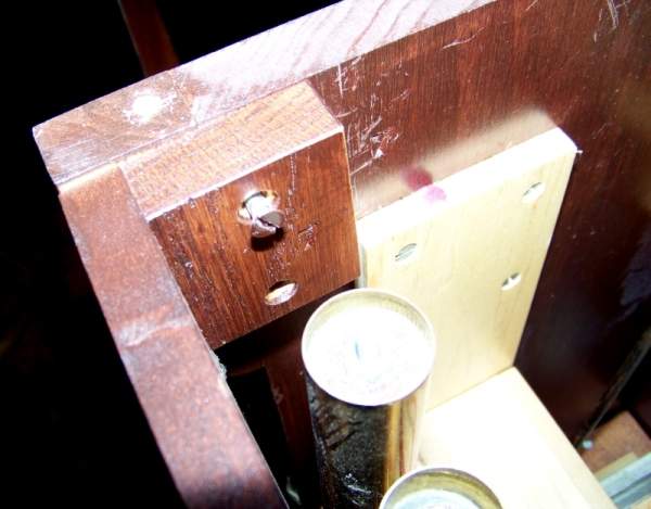
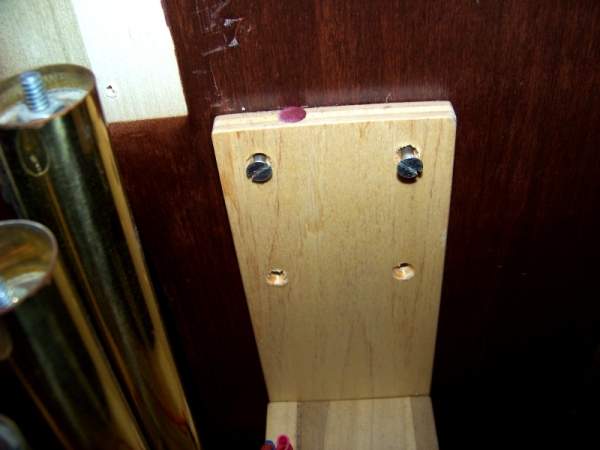
Step 4. Pull the four screws holding the top-front panel in
place and remove the top-front.
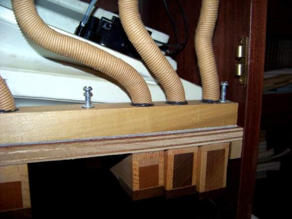
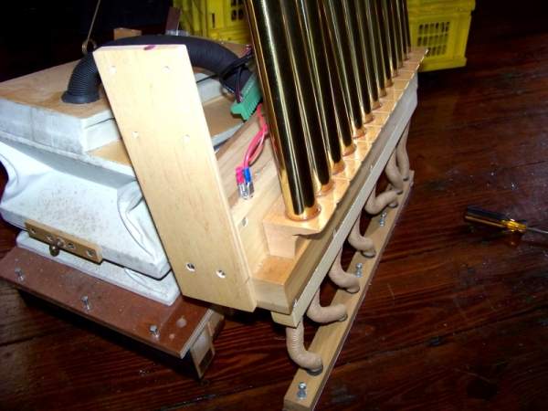
Step 5. Pull the three screws holding the lower end of the
tube assembly to the bellows-and-lower-pipe assembly. You may also
want to remove the upper screws as well.
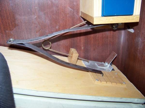
Step 6. Remove the leaf spring. CAUTION: Note the slot in
which the spring is installed. If you reinstall it in a different
place you will change the organ's pressure setting, and may affect
the pipe voicing and/or tuning! Loosen the top of the relief valve
spring.
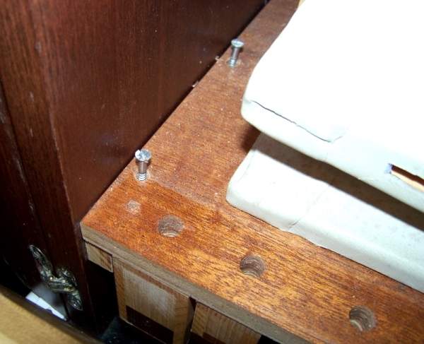
Step 7. Pull the eight screws holding the
chest-and-upper-pipe-assembly to the case sides. You can now slide
the upper assembly forward or backward to access the lower
assembly screws.
The 20 electric solenoid valves are located inside the chest. I
have not opened the chest to examine them, but I am certain that
they are Reisner 601 valves manufactured by OSI. These are high
quality valves designed and constructed for major church and
theater pipe organs, and should have a long life. The possible
"rebuild" would be replacing the felt disks and their leather
faces. Replacements should be readily available for your lifetime.
Step 7. Loosen the six screws holding the
bellows-and-lower-pipe assembly to their mounting strips.
Step 8. You can now slide the two assemblies out of the
front of the case. The two assemblies are connected by the main
air duct which is held in place with epoxy, and you should not
attempt to break this connection without considerable forethought.
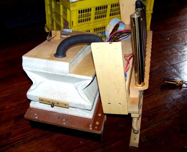
The air supply unit consists of a double acting pumping bellows
and a reservoir bellows. The pumping chambers are 9 inches by 15
inches. The reservoir measures 14 inches by 6 inches with about 3
inches of movement. The crank stroke is about 55 mm (2.2 in.)
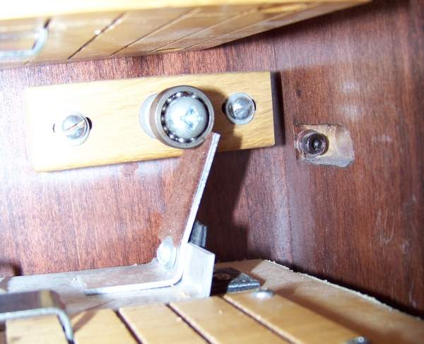
The pressure relief valve is a metal flap with a turned-up tab. It
is mounted on the reservoir, just below the battery mount. When
the reservoir is full, the operating tab contacts a ball-bearing
roller and opens the valve.
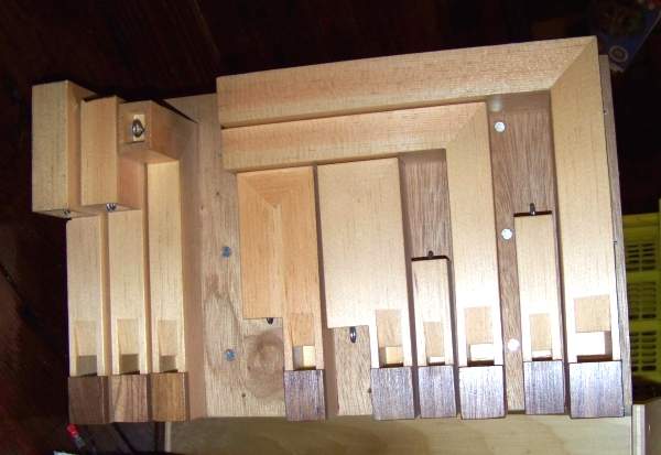
Bottom view of the lower pipes. You can see that the lowest two
pipes are paired with short pipes producing overtones, making this
a 22-pipe, 20 note organ.
Links to additional OSI Street Organ information:
My main Mechanical Music page